This article is a part of a series on Packet Traveling — everything that happens in order to get a packet from here to there. Use the navigation boxes to view the rest of the articles.
Packet Traveling
We’ve looked at what it takes for two hosts directly connected to each other to communicate. And we’ve looked at what it takes for a host to speak to another host through a switch. Now we add another network device as we look at what it takes for traffic to pass from host to host through a Router.
This article will be the practical application of everything that was discussed when we looked at a Router as a key player in Packet Traveling. It might be worth reviewing that section before proceeding.
We will start by looking at the two major Router Functions, then see them in action as we look at Router Operation.
To discuss our way through these concepts, we will use the following image. We will focus on R1, and what is required for it to forward packets from Host A, to Host B and Host C.

For simplicity, the MAC addresses of each NIC will be abbreviated to just four hex digits.
Router Functions
Earlier we mentioned that a Router’s primary purpose is to facilitate communication between networks. As such, every router creates a boundary between two networks, and their main role is to forward packets from one network to the next.
Notice in the image above, we have R1 creating a boundary between the 11.11.11.x network and the 22.22.22.x network. And we have R2 creating a boundary between the 22.22.22.x and 33.33.33.x networks. Both of the routers have an interface in the 22.22.22.x network.
In order to forward packets between networks, a router must perform two functions: populate and maintain a Routing Table, and populate and maintain an ARP Table.
Populating a Routing Table
From the perspective of each Router, the Routing Table is the map of all networks in existence. The Routing Table starts empty, and is populated as the Router learns of new routes to each network.
There are multiple ways a Router can learn the routes to each network. We will discuss two of them in this section.
The simplest method is what is known as a Directly Connected route. Essentially, when a Router interface is configured with a particular IP address, the Router will know the Network to which it is directly attached.
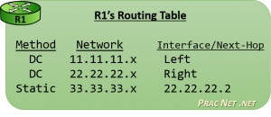
For example, in the image above, R1’s left interface is configured with the IP address 11.11.11.1. This tells R1 the location of the 11.11.11.x network exists out its left interface. In the same way, R1 learns that the 22.22.22.x network is located on its right interface.
Of course, a Router can not be directly connected to every network. Notice in the image above, R1 is not connected to 33.33.33.x, but it is very likely it might have to one day forward a packet to that network. Therefore, there must exist another way of learning networks, beyond simply what the router is directly connected to.
That other way is known as a Static Route. A Static Route is a route which is manually configured by an administrator. It would be as if you explicitly told R1 that the 33.33.33.x network exists behind R2, and to get to it, R1 has to send packets to R2’s interface (configured with the IP address 22.22.22.2).
 In the end, after R1 learned of the two Directly Connected routes, and after R1 was configured with the one Static Route, R1 would have a Routing Table that looked like this image.
The Routing Table is populated with many Routes. Each Route contains a mapping of Networks to Interfaces or Next-Hop addresses.
Every time a Router receives a packet, it will consult its Routing Table to determine how to forward the packet.
Again, the Routing Table is a map of every network that exists (from the perspective of each router). If a router receives a packet destined to a network it does not have a route for, then as far as that router is concerned, that network must not exist. Therefore, a router will discard a packet if its destination is in a network not in the Routing Table.
Finally, there is a third method for learning routes known as Dynamic Routing. This involves the routers detecting and speaking to one another automatically to inform each other of their known routes. There are various protocols that can be used for Dynamic Routing, each representing different strategies, but alas their intricacies fall outside the scope of this article series. They will undoubtedly become a subject for future articles.
That said, the Routing Table will tell the router which IP address to forward the packet to next. But as we learned earlier, packet delivery is always the job of Layer 2. And in order for the Router to create the L2 Header which will get the packet to the next L3 address, the Router must maintain an ARP Table.
Populating an ARP Table
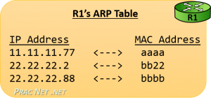
The Address Resolution Protocol (ARP) is the bridge between Layer 3 and Layer 2. When provided with an IP address, ARP resolves the correlating MAC address. Devices employ ARP to populate an ARP Table, or sometimes called an ARP Cache, which is a mapping of IP address to MAC addresses.
A router will use its Routing Table to determine the next IP address which should receive a packet. If the Route indicates the destination exists on a directly connected network, then the “next IP address” is the Destination IP address of the packet – the final hop for that packet.
Either way, the Router will use a L2 header as the vessel to deliver the packet to the correct NIC.
 Unlike the Routing Table, the ARP Table is populated ‘as needed’. Which means in the image above, R1 will not initiate an ARP Request for Host B’s MAC address until it has a packet which must be delivered to Host B.
But as we discussed before, an ARP Table is simply a mapping of IP addresses to MAC addresses. When R1’s ARP Table will be fully populated, it will look like this image.
Once again, for simplicity, the images in this article are simply using four hex digits for the MAC addresses. In reality, a MAC address is 12 hex digits long. If its easier, you can simply repeat the four-digit hex MAC address three times, giving R2’s left interface a “real” MAC address of bb22.bb22.bb22.
Router Operation
With the understanding of how a Router populates its Routing Table and how a Router intends to populate its ARP Table, we can now look at how how these two tables are used practically for a Router to facilitate communication between networks.
In R1’s Routing Table above, you can see there are two type of routes: some that point to an Interface, and some that point to a Next-Hop IP address. We’ll frame our discussion around a Router’s operation around these two possibilities.
But first, we will discuss how Host A delivers the packet to its Default Gateway (R1). Then we will look at what R1 does with a packet sent from Host A to Host B, and then another packet that was sent from Host A to Host C.
Host A getting the Packet to R1
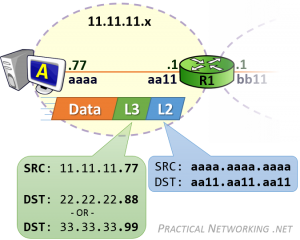
 In both cases, Host A is communicating with two hosts on foreign networks. Therefore, Host A will need to get either packet to its default gateway — R1.
Host A will create the L3 header with a Source IP address of 11.11.11.77, and a Destination IP address of 22.22.22.88 (for Host B) or 33.33.33.99 (for Host C). This L3 header will serve the purpose of getting the data from ‘end to end’.
But that L3 header won’t be enough to deliver the packet to R1. Something else will have to be used.
Host A will then encapsulate the L3 header in a L2 header which will include a Source MAC address of aaaa.aaa.aaaa and a Destination MAC address of aa11.aa11.aa11 — the MAC address which identifies R1’s NIC. This L2 header will serve the purpose of delivering the packet across the first hop.
Host A will have already been configured with its Default Gateway’s IP address, and hopefully Host A will have already communicated with foreign hosts. As such, Host A more than likely already had an ARP Table entry with R1’s MAC address. Conversely, if this was Host A’s first communication with a foreign host, forming the L2 header would have been preceded with an ARP Request to discover R1’s MAC address.
At this point, R1 will have the packet. The Destination IP address of the packet will either be 22.22.22.88 for the communication sent to Host B, or 33.33.33.99 for the communication sent to Host C. Both of those destinations exist in R1’s Routing Table — the difference is one Route points to an Interface and the other Route points to a Next-Hop IP.
Routes pointing to an Interface
A Route in a Routing Table that points to an Interface was typically learned because the Router was Directly Connected to the network. If a packet’s Destination IP address is in a network which is directly connected to the router, the Router knows they are responsible for delivering the packet to its final hop.
The process is similar to what has been discussed before. The Router uses the L3 header information to determine where to send the packet next, then creates a L2 header to get it there. In this case, the next (and final) hop this packet must take is to the NIC on Host B.

The L3 header will remain unchanged — it is identical to the L3 header created by Host A.
What is different, is the L2 header. Notice the Source MAC address is bb11.bb11.bb11 — R1’s right interface MAC address. The old L2 header which Host A had created to get the packet to R1 was stripped off, and a new L2 header was generated (by R1) to deliver it to the next NIC.
The Destination MAC address is, of course, bbbb.bbbb.bbbb — the MAC address for Host B.
Routes pointing to a Next-Hop address
For the packet from Host A sent to Host C, the Destination IP address will be 33.33.33.99. When R1 consults its Routing Table, it will determine that the next-hop for the 33.33.33.x network exists at the IP address 22.22.22.2 — R2’s left interface IP address.
Effectively, this tells R1 to use a L2 header which will get the packet to R2 in order to continue forwarding this packet along its way.
Since the current “hop” is between R1 and R2, their MAC addresses will make up the Source and Destination MAC addresses:

Again, the L3 header remains unchanged, it includes the same Source and Destination IP addresses initially set by Host A — these addresses represent the two “ends” of the communication. The L2 header, however, is completely regenerated at each hop.
Should R1 not have R2’s MAC address, it would simply initiate an ARP Request for the IP address in the route: 22.22.22.2. From then on, it will have no problems creating the proper L2 header which will get the packet from R1 to R2.
As the process continues, R2 will finally receive the packet, and then be faced with the same situation that R1 was in for the example above — deliver the packet to its final hop.
This process can be continued as needed. Had Host A been trying to speak to Host X which had 10 routers in the path, the process would have been identical. Each transit Router in the path would have a Route mapping Host X’s network to the next-hop IP in the path. Until the final router which would be directly connected to the network Host X resided in. And that final router would be responsible for delivering the packet to its final hop — Host X itself.


